Part I: A simple synthesizer in Pure Data – Part I
The next steps:
What we are going to do now is to add an ADSR envelope to our synthesizer and then allow it to play more than one note simultaneously.
We also have a lot of new concepts to introduce, including some that are very basic and that, if you tinkered a little with your patch and with pd in general after the first tutorial, you may be already familiar with.
Adding the envelope
| ADSR Envelope |
|---|
|
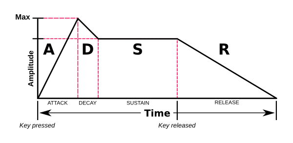
Roughly speaking, an envelope changes the signal amplitude through time. The ADSR envelope does this based on four variables: Attack, Decay, Sustain and Release. Excluding Sustain, they all represent a duration in time. Sustain represents amplitude, not duration. Here's a quick explanation:
- Attack represents the time from the key press to the moment the signal reaches full amplitude. Amplitude starts at zero (silence) and, during the amount of time given by the Attack variable, rises to one (maximum amplitude).
- Decay comes in after Attack and represents the amount of time for the signal to reach the amplitude given by the Sustain variable.
- Sustain is the amplitude that will be maintained while the key is down.
- After releasing the key, Release is the amount of time before the amplitude drops to zero.
 ADSR Envelope |
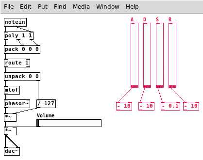
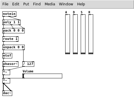
Start by adding four sliders (Ctrl+Shift+H for horizontal or Ctrl+Shift+V for vertical) and giving them the labels A, D, S and R. This can be accomplished by right-clicking the sliders and choosing Properties, if you don't remember. In this dialog, we are also going to set the range of each slider and maybe set their send symbols as well. We will get into send soon, but let's talk about ranges first.
In the Properties dialog, you will notice a button labeled lin. When clicked on, this button's label will toggle between lin and log, representing linear and logarithmic scales, respectively. You may also have noticed that when changing from lin to log, range fields set to zero will change to a non-zero value.
| Linear and Logarithmic scales |
|---|
|
Logarithmic scales are very useful when dealing with a large range of quantities and when dealing with most things related to human perception. The decibel, used frequently to measure sound pressure levels, is a logarithmic unit and our own musical scale is also a logarithmic scale of pitches. I'll give now an example of how useful it also can be for quantities related to time.
Imagine that you want to select a value between 1 millisecond and 20 seconds for the duration of an event using a slider that is 128 pixels wide (no need to imagine too much, this is exactly what you want to do now). While the perceived difference between a sound that decays in 10ms and other that decays in 110ms (difference of 100ms) is very pronounced, the difference between 19,000ms and 19,100ms (also 100ms) will hardly be perceived by any human being.
In a linear scale, each pixel you move in this slider will represent ~156ms. This means that you will have, perception-wise, a very low precision when dealing with small values while you'll have a precision higher than you need with the higher values. The logarithmic scale fixes this problem by giving more space to the lower values and less space to the higher ones.
When using a linear scale, equally spaced markings in the scale will represent equal distances between values. In a logarithmic scale equally spaced markings will represent equal proportions between values.
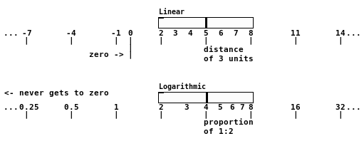 Equal distances vs. equal proportions Since we can't establish a proportion between zero and other values, your slider will never be able to output a zero in log mode. No finite value in dB, for example, represents absolute silence.
|
You can choose whatever ranges and scales you want now. For time-related sliders (Attack, Decay and Release), I think a range from 0 to 10 seconds is a good choice. Remember that you need to use milliseconds, so it's a range from 0 to 10,000. For Sustain there is no choice, really, because you need a value between 0 and 1.
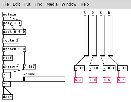
If you choose linear scales, then just fill the Properties dialog with the appropriate values and you're done. With logarithmic scales, however, we need to add an offset so we can have a range that includes zero. Just move the range a little higher (e.g., 10 to 10,010 in time sliders and 0.1 to 1.1 in Sustain), then connect each slider to an operator that will give you a range starting from zero (in the given example, - 10 for time-related sliders and - 0.1 for Sustain).
Sliders with offset values
Now we need to send, the values from the sliders so we can receive them elsewhere. It will be slightly different depending on whether you offset the output from the sliders or not.
| send and receive |
|---|
|
The objects send and receive (also abbreviated to, respectively, s and r) can:
- make your patch cleaner by removing wires from inconvenient places;
- establish communication between your patch and other patches running at the same time.
First you create a send object with a unique name passed as argument and connect some x object to it. Then you create a receive object with the same name and connect it to some y object. This will work exactly the same as if x and y were connected directly, with the difference that y can even reside in another patch!
Of course, this also means that you cannot run two instances of this patch (the one with send) simultaneously, because there would be two send objects with the same name and this is not allowed. You can, however, use as many name-fellow receive objects as you like.
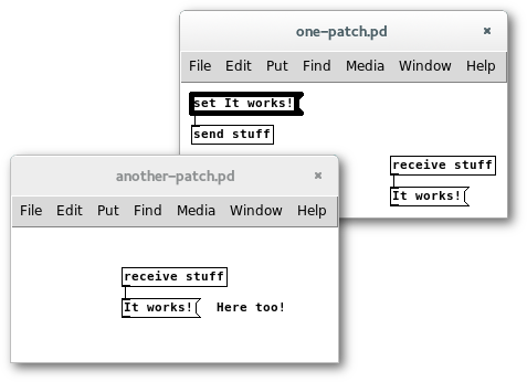 send send and receive in the same patch and between two different patches When you open the Properties of some objects, you have the option of setting a send symbol and a receive symbol from there. This will work exactly like connecting it to send and receive objects, but allow a cleaner (and more obscure) connection. To give a tip about the existence of such connections, objects using this method appear without their inlets and/or outlets (depending if you are using receive and/or send symbols) so you know they are silently sending or receiving stuff. Their invisible inlets or outlets are still usable though.
There's a workaround to the problem with multiple instances of the same patch with a send object, but I think it's too early to talk about that. It's about using the $0 variable, take a look at this if you're curious. |
If you're using only the sliders, without adding offsets to the values, just open the Properties dialog of each of your sliders and set your send symbols to a, d, s and r. I think you know which is which. Have in mind the fact that pd is case-sensitive, so 'a' is not the same as 'A'.
Note the absence of outlets in the sliders, due to the usage of
send symbols
If you have added the offsets, then you cannot send your values directly from the sliders. You will need to add four send objects (let's use the abbreviated version: s): s a, s d, s s and s r, and then connect each of the offset values to the corresponding send.
Using
send objects
Now, because we want to be able to play more than one note (eventually), we're going to take a part of our patch and move it to an abstraction.
| Abstractions and Subpatches |
|---|
|
Basically, abstractions and subpatches allow you to use one entire patch as an object inside another patch.
In the case of the abstraction, the patch that will be used as an object is stored in another file. If you create a patch and save it in the same folder as the patch you are currently working on, you can then invoke it by naming an object after the patch you created, without the .pd extension. If you create multiple instances of this object, saving the changes will apply them to all of the instances, naturally.
A subpatch is almost the same, but it's not stored in another file and the changes applied to one of them are not reflected in others, even if they have the same name. They are created by calling an object pd followed by an optional name.
The objects created using these methods can have inlets and outlets represented internally by inlet, inlet~, outlet and outlet~ objects. The order of inlets and outlets will be the same, left to right, as the order the objects appear inside the abstraction or subpatch.
|
Go to File→New (Ctrl+N). Now, in this new window, File→Save As... (Ctrl+Shift+S) and save it to the same folder as your patch with the name note.pd (you can write just note). In the near future we'll also be using another abstraction so, in the same window repeat the Save As... procedure to save it as adsr.pd. Now, you should have, in the same folder as your main patch, two empty patches named note.pd and adsr.pd. You can close this window now and go back to your main patch.
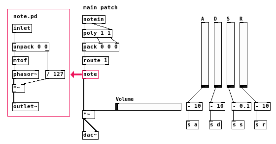
Create a note object and place it in some empty spot. To edit this subpatch, you can either right-click on it and select Open, or left-click it while in Execute Mode. Just open it. Yes, I just made you close and open the same file again, but with one difference: when you open an abstraction from a patch that contains it, every change you make to it is instantly effective to this particular instance of the abstraction. When you save it, the changes are globally applied.
To prove it, as soon as you open note for editing, insert both an inlet and outlet~ objects (we want to input control data and output signal data) with some empty space between them. As soon as you add the objects you will notice that the inlet and outlet will appear instantly in the object inside your main patch.
In the main patch, select everything from unpack to the first *~ and cut (Ctrl+X), then paste inside the abstraction (Ctrl+V). Place the note object in the empty space where the cut objects were and connect it so that it replaces that group of objects. Inside the abstraction, connect the inlet to unpack and *~ to the outlet~.
Remember to save both the abstraction and the main patch. Right now, our patch is doing the exact same thing it did before we started but, with the changes that we made, it will be a lot easier to fulfill our objectives.
The fun starts now. No, it's true.
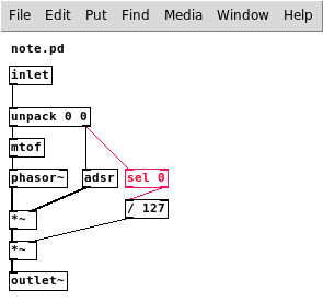
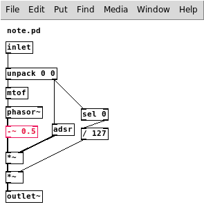
As you know, the *~ inside note.pd sets the amplitude of each note depending on its velocity. Now we want something more complex than that and that's where we will insert the adsr abstraction. When we're done, this object will be responsible for changing the amplitude of our oscillator dynamically, following the envelope defined by the sliders in the main patch.
- Inside note.pd, insert the adsr object somewhere;
- open the adsr.pd abstraction and insert an inlet and an outlet~;
- back in note.pd, insert a new *~ between phasor~ and the existing *~, deleting the existing connection and connecting the new *~ to both (use the left inlet);
- connect the second outlet of unpack to adsr and then the latter to the *~ you just created.
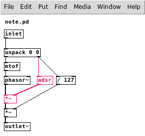
The current state of note.pd
With adsr properly placed and connected, most of the remaining work will be done inside adsr.pd. I'll split our next step into 3 parts so that, at the end of each part, you can test if the corresponding phase of the envelope is working as intended. At the beginning of each part, I'll introduce the needed objects.
Before starting, insert four receive objects in adsr.pd (again, using the short version: r): r a, r d, r s and r r. This is how we'll read values from the sliders in the main patch.
Attack
In this part, you need to become acquainted with select, trigger, float and line~.
| select |
|---|
|
The select object (or the short version, sel) will compare the input with its arguments. Each of its outlets will send a bang if the input is equal to the respective argument. There's an extra outlet from which the input value will come out, untouched, in case no argument is equal to it.
If there's only one argument, the value can be changed with the right inlet.
|
| trigger |
|---|
|
trigger (short version: t) is used when actions must be performed in a specific order. You can specify any number of arguments and there will be an outlet for each of them. The arguments will represent the type of the output for the respective outlet. The outlets will activate from right to left, so the last data type you wrote will be the first to come out.
For now, we must be aware of two types that can be used as argument to trigger: bang and float (you can use b and f, respectively, just as well).
- bang will output a bang it does not matter what the input is;
- float will output the input as a number.float
|
| float |
|---|
|
float, or f, just stores a number. When create an object and name it with just a number and nothing else, it is also a float object, but in this case it is initialized to the value you gave. It will output the stored value when it receives a bang in its left inlet.
When it receives a number, it will change its stored value. If the number is received by the left inlet, it will instantly output this new value. The right inlet will, in its turn, silently change the stored value without outputting anything. This is basically what this hot and cold inlets thing is all about. We'll get to this subject soon. |
| line and line~ |
|---|
|
Both objects will output a stream of numbers that will reach the target value in the specified ramp time. You can pass the ramp time to the second inlet and then pass the target to the first inlet or you can pass both values to the first inlet together. Two important things to remember:
- it will only start the ramp when a value is passed to its first inlet (the one in the left), also called the hot inlet. We'll talk about that soon;
- it will not remember the last ramp time you used, meaning that you will have to pass one every time.
If you pass a target alone, without passing a ramp time, it will jump immediately to that value.
While line~, like other signal objects, outputs with a frequency equal to your system's sample rate, the output rate of line can be set by passing it as an argument (the first argument you pass is the initial value and the second is the output rate or grain) or by passing it to the third inlet. The default is 20ms.
|
In my instructions, if I ask you to connect an object to another that is not in your patch yet, it means that you must create it in that moment and then make the connection. Make sure you have lots of space between inlet and outlet~ before starting.
In adsr.pd:
- insert, just above outlet~, a line~ object and connect the latter to the former;
- connect the inlet to a sel 0;
- connect the right outlet of sel 0 to a t b b b (a trigger with three bangs);
- connect the third outlet (the first from right to left) to a 0 (just a zero) and the second to a pack 1 0;
- connect r a to the right inlet of pack 1 0;
- connect both 0 and pack 1 0 to the left inlet of line~.
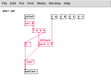
adsr.pd with
Attack working, but nothing else
The attack is ready to be tested! Let me explain what we did.
The line~ object is the heart of this abstraction. In the end, we'll have three pack objects to group target and ramp time values and then send them to line~. Each one of the pack objects will be responsible for one phase of the envelope, so you could add a comment above the one we just inserted (Ctrl+5) and label it Attack, so you know it's function in the future.
The value coming from the inlet and entering sel 0 is the velocity of the note played. Every time you receive a note off event (velocity 0), the left outlet of sel 0 will send a bang. Since we're interested, at least for now, in the attack of the note, we connected the trigger to the right outlet of sel 0. This outlet is activated every time we get a value that is not 0, which means a key was pressed. The output of this outlet is not a bang, but the value that came in. Since our trigger only contains bangs, we basically ignored the value that came out and converted it to bangs.
The first bang from our trigger is connected to the 0, so it will immediately set the line~ value to zero. The second bang will pack the value 1 together with the value of the Attack slider. When line~ receive these values, it will start a ramp from its current value, zero, to 1 with the duration received from the Attack slider. We intentionally left an unconnected outlet in the trigger.
Decay (and Sustain)
We will now get to know the delay object and then I'll finally talk about hot and cold inlets.
| delay |
|---|
|
The delay object outputs a bang after a delay that is passed to it, in milliseconds, as argument or by its inlets. You can change the delay time by sending a value to any of the inlets, but the right inlet (cold inlet) will not trigger the delay immediately, while the left inlet (hot inlet) will. You can just send a bang to its left inlet to trigger a delay with the duration that was previously set.
|
| Hot and cold inlets |
|---|
|
The intended way of entering data to objects with more than one inlet is from right to left. Pure Data kind of enforces this by having only one of the inputs, the left one, to cause the object to output data. This is why we call it the hot inlet. All the other inlets are cold inlets, meaning that they don't produce output when you pass information to them. He have already seen a lot of this happening in our work, but there was no need to worry in most cases, because pd acts consistently.
Right at the beginning of our main patch, we used objects that would not work correctly if their inputs came in the wrong order, like pack and poly. The reason why they worked is that the output of the objects that we connected to them also came, conveniently, from right to left. When we use a pack to which the inputs will come from separate objects, we'll have to take care to send them in the correct order. This is the kind of situation where the trigger object shines.
|
In adsr.pd:
- connect the remaining unused outlet of t b b b to a delay object;
- connect
r a to a + 1 (left inlet) and then the + 1 to the right inlet of the delay you just created;
- connect delay to the first inlet of a pack 0 0 0 (you can put the comment Decay above it);
- connect r d to the third inlet of the pack object and r s to the second;
- connect pack 0 0 0 to a route 0 object;
- finally, connect this route 0's left outlet to line~'s left inlet.
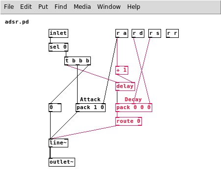 Decay
Decay and
Sustain working
Decay and Sustain are both working and ready to be tested.
The objective of the delay object here is to wait until the Attack phase is over to kick in with the Decay. That's why we connected the Attack slider to set the delay time. The + 1 is here because without it, when the Attack value is minimal, Decay comes in too early for some reason.
There's also another hack here. We used a pack with three arguments where only two values were needed. This is because we want to avoid inputting data to the hot inlet while using our sliders. The pack object as we created it will only output something when it receives a bang from delay. If we had only two inlets in pack, r s would need to be connected to the hot inlet and this would cause undesirable output every time the slider value changed. To eliminate the unused value, we used a route 0. If you don't understand this, just read the route explanation in the first part of the tutorial again. This is not exactly the purpose of the existence of route, but it does the trick.
Release
In this last part, we also have some work to do in note.pd, but let's finish everything in adsr.pd first so we don't have to come back.
You may have noticed that, until now, we have only used the right outlet of sel 0, because this outlet shows us when a key is pressed. Now we are interested in knowing when a key is released, so I suggest that you move the r r object to the left side of the patch before following the next instructions, so it's closer to the left inlet of sel 0.
- Connect the left outlet of sel 0 to a stop message (remember it's a message (Ctrl+2), not an object) and connect this message to the left inlet of our delay
- also connect the left outlet of sel 0 to a new pack 0 0 object. You can put the comment Release above it;
- connect this pack 0 0 to the left inlet of line~;
- connect r r to the right inlet of the same pack 0 0 object.
We're done with adsr.pd.
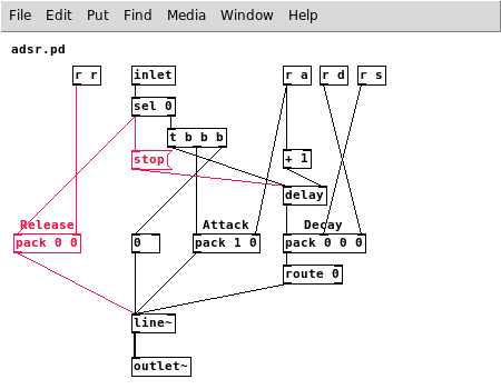
Release not working yet
The reason why Release is not working yet is that we programmed note.pd to multiply the signal by 0 when the key is released and this causes the note to silence immediately. Now we are going to make the right operand of this multiplication change only when a key is pressed and not when it is released.
In note.pd:
- break the connection between unpack and / 127;
- connect the right outlet of unpack to a sel 0 object;
- connect the right inlet of this sel 0 to / 127.
Now only non-zero values will reach this division and the problem is solved.
Release working
The stop message that we used in adsr.pd is a message that delay understands as an order to interrupt its countdown, so the bang does not get triggered. We need that because the note can be released during the Attack phase, before Decay starts, and we would have a problem because this delay would trigger the Decay phase after Release had already started.
We're done with our envelope now! You can experiment with different configurations and you may be surprised by how much applying an envelope can transform the perception of a sound.
Polyphony
To add polyphony to our synthesizer will be a very easy task now, because we're using abstractions that we can easily reuse. Anyway, before we start adding stuff, we need to make a small adjustment to the sawtooth wave that we've been using.
You should remember, from the last tutorial, that phasor~ generates values from 0 to 1. This means that it only “occupies” half of the “signal space” available, that is from -1 to 1. When two signals are mixed together (two sounds played together), what happens is simply that each sample from one signal gets added to the corresponding sample of the other signal. Knowing this, it's not hard to understand that the minimum possible sample value from mixing two of those sawtooth waves is 0 (when both values are 0) and the maximum is 2 (when both values are 1). We would be not only wasting space, but also using space that is not available and therefore clipping the signal. When there are values greater than one, those values are simply considered to be 1 and this is what we call clipping.
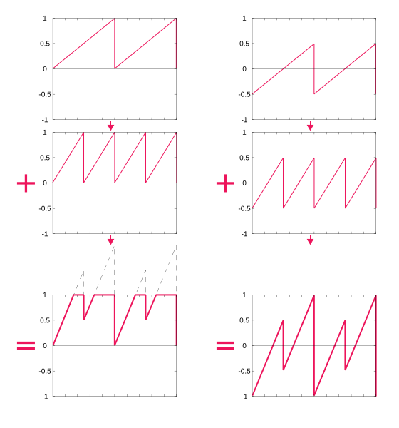
The sum of two sawtooth waves with a 1:2 frequency ratio. In the left we have a range from 0 to 1 and in the right from -0.5 to 0.5.
When the signal is clipped, the waveform changes and so do the timbre of the sound produced. Sometimes this is the desired effect, but that's not our case now, so we're going to insert a –~ 0.5 object after the phasor~ in note.pd.
phasor~ with an offset
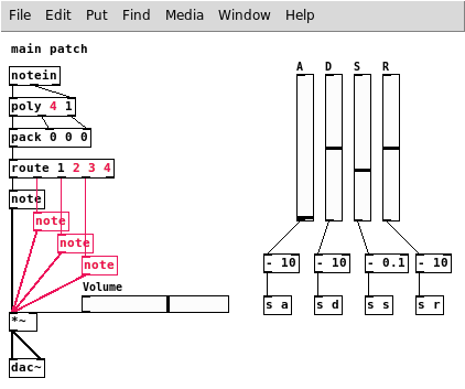
Now on to the last steps, in the main patch:
- change poly first argument to the number of voices you want, e.g., poly 4 1 for four voices;
- give route one argument for each voice you have, e.g., route 1 2 3 4 for four voices;
- duplicate the note object (Ctrl+D) as many times as needed, one for each voice;
- connect each route outlet to one of the note objects, leaving the rightmost outlet alone;
- connect every note object to the *~ object, where the first note was already connected.
Finished!
You're done! Just save your patch and have fun playing!
Here's a picture of the finished patch with all the abstractions:
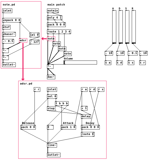
When making changes to our abstractions in the future, having multiple instances in use will not be a good idea because, as I said before, the changes you make in an abstraction are only applied to all of them when you save it, but are immediately applied to the particular instance that is currently opened. The best way to make changes to a note object is to just change poly's first argument to 1 and leave everything else intact, then open the note.pd abstraction from the first note object (right-click→Open or left-click in Execute Mode). Your synthesizer will go back to a monophonic state while you make your changes, but you'll be able to test each change instantly. When you are pleased with the result, just save your abstraction, then change back the first argument of the poly object to the number of voices you have.
That's all for today
Now we're able to do a lot of different sounds using our envelope, but that's not enough. In the next tutorial, we will create a simple dynamic filter to finally have a subtractive synthesizer. As a bonus, I'll also show how to create a simple and clean user interface to make your synthesizer more user-friendly. I hope you're finding this tutorial series useful! Your feedback is always welcome.
Written by Eduardo Mezêncio