Part I: Creating a simple synthesizer in Pure Data - Part I
Part II: Creating a simple synthesizer in Pure Data - Part II
The steps:
We now have two important steps to finish our little project: the first is to add a filter that will finally turn our synthesizer into a subtractive synthesizer and the second is to create a simple user interface to make our patch more intuitive and pleasant to the end user.
Adding the filter
So we&'re here, finally. As you may remember from Part I, subtractive synthesis is a kind of synthesis where we take a sound with lots of harmonics (even white noise) and filter some of them out, thus creating a rich sound that would practically impossible to obtain with additive synthesis. Additive synthesis would start from total silence and then add the desired harmonics, one by one.
| Filter |
|---|
|
Filters are used to remove or attenuate frequencies from a signal. Since Pure Data has objects that implement different types of filters, you don't need to know exactly how this is achieved, but it's important to know what each type of filter does.
The simplest filters that you can create in Pure Data are:
-
Low pass filter: allows only frequencies that are below a given cutoff frequency to pass, meaning that the frequencies above are filtered out. Implemented by the lop~ object.
-
Band pass filter: allows frequencies that are close to a given center frequency to pass, while filtering out all the others. The width of the band will be given by the Q factor. The greater this dimensionless parameter is, the narrower the band will be. Implemented by the bp~ object.
-
High pass filter: same as the low pass filter, but inverted. Frequencies above the cutoff frequency are allowed to pass, while frequencies below are filtered out. Implemented by the hip~ object.
These 3 objects are very easy to use and you can check the documentation to learn how to use them. The reason why I'm not explaining this here is simple: we are not going to use any of these objects in our synthesizer. All of the objects listed above take a frequency (cutoff frequency in low pass / high pass filters and center frequency in band pass filter) as control data input. Using control data means that it will not be possible to change this frequency smoothly throughout time as we want to do (you'll see why soon).
|
| vcf~ |
|---|
|
This is the object that we are actually going to use to implement our filter. vcf stands for voltage-controlled filter. In 'real life', a voltage-controlled filter can change its cutoff frequency by means of a voltage applied to its inputs, which may sound strange since we can't input voltage to our Pure Data objects. In Pure Data you can change the cutoff frequency by inputting a signal.
The vcf~ has 3 inlets: the first is the signal you want to apply the filter to, the second is the signal data that will control the cutoff frequency and the third is a control data input for the Q factor.
The first outlet will output the result of a band pass filter applied to your original signal, while the second outputs a low pass filter.
|
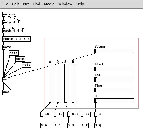
Let's start by adding some sliders to the main patch. You can add four sliders (Ctrl+Shift+H for horizontal and Ctrl+Shift+V for vertical, but you should already know that) and name them, respectively, Start, End, Time and Q. Here's the configuration that I'll recommend for now:
-
Start: set send symbol to start and output range from 20 to 20000 in log mode
-
End: set send symbol to end and output range from 20 to 20000 in log mode
-
Time: set send symbol to time and output range from 10 to 10000 in log mode
-
Q: leave send symbol blank and set output range from 1 to 256 in log mode, then connect the slider to a - 1 object and this last object to a s q object
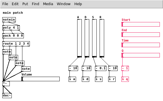
The output of Start and End are frequencies in hertz. The filter center frequency will ramp from Start to End in the time interval given by Time, in milliseconds, every time a note is played. Logarithmic scales are great for all of these values, even time and Q factor, because you can have a finer control over the small values. We want to be able to output 0 as Q factor, so we need the - 1 object.
When we're done, you can tweak all the values as you see fit. Other than the frequency values, I choose the maximum values in a somewhat arbitrary manner.
We are done with our main patch. Let's move on to note.pd.
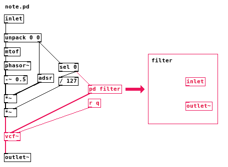
The first thing to do in note.pd is to add the filter, by creating a vcf~ object and placing it between the last signal multiplication object (*~) and the outlet~ object. You need to connect the multiplication to the first inlet of the vcf~ and then the first outlet of the vcf~ to the outlet~.
The second and third inlets of the filter are for center frequency and Q factor, respectively. Controlling the center frequency will be a slightly more complex task, so we're going to put it in a subpatch. Create a pd filter object and a new window will open for you to edit its contents (you can open it anytime by clicking the object in Execute Mode). In this window you need to create only two objects for now: an inlet and an outlet~, then just close the window. Now you'll notice the pd filter has an inlet and an outlet, so let's connect it. Connect the second outlet from the sel 0 object to the inlet of pd filter and the outlet of pd filter to the second inlet of the vcf~ object.
The Q factor part is easier. Just create a r q object and connect it to the third inlet of the vcf~.
Now, all the remaining work to make our filter functional is inside of the pd filter subpatch. Just in case you don't remember, the outlet of sel 0 that we connected to the inlet of our subpatch will output a number when a note is played, but nothing when the note is released. This number is the midi velocity of the note, but it does not matter for our current purpose.
So, let's work inside the subpatch. Start by adding below the inlet, in this order, the following objects: a bang, an f and then a t b f. Connect the first outlet of each object to the first inlet of the next, starting from the inlet object. Then create a r start object and connect it to the second inlet of the f object.
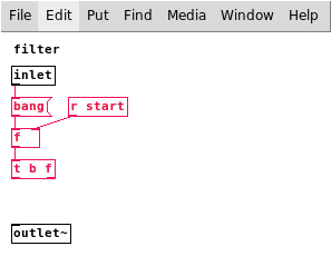
Each time a note is played the bang will be activated and it will trigger the number stored in f (the value from the Start slider in the main patch) and then another bang. This will be used to set the start value for the frequency ramp and then get it going.
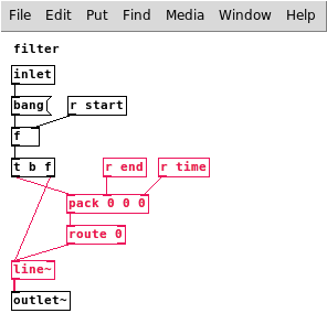
Now create a pack 0 0 0 object and connect the first outlet of the t b f object to its first inlet. Create an r end and an r time objects and connect them to the second and third inlets, respectively. Create a route 0 object and connect the first outlet from pack 0 0 0 to its first inlet and then its first outlet to the first inlet of a line~ object. The second outlet from the t b f object will also be connected to the first inlet of this line~ object. Finally, connect the line~ object to outlet~.
Believe it or not, we are done with the filter. Yes, it was that easy. If you have problems, try to reload your patch, because sometimes the changes are not applied to all instances of edited abstractions.
What happens here is that t b f sends the value of Start to line~, making it jump immediately to that value. Then the pack / route objects are used to send a package with both the End and Time values, so line~ starts a ramp to the End value that takes Time milliseconds to complete. This kind of usage of pack and route together was described and explained in the part 2 of the tutorial, inside of the adsr abstraction.
Creating an user interface
If you came all the way from the beginning of this tutorial, you probably had already enough experience to notice that the focus of Pure Data is not exactly to make things look good. But that does not means you need to see all the inner workings of your patch while you are using it. One of the most interesting uses of Pure Data is for live performance and you would imagine a nice interface would make things a lot easier for the performer.
I'll show three different things you can do to organize your patch and make it look better, so you can use your creativity to customize your patch to your liking.
Graph-On-Parent
Graph-On-Parent allows you to change the way a subpatch or abstraction will appear in the patch that contains it. Instead of appearing as a normal object with its name, it can appear as a part of the subpatch/abstraction contents or as a graph. We're going to use the former here.
Open your main synthesizer patch, then select everything (Ctrl+A) and cut (Ctrl+X). Now create a new object in this empty canvas called pd synth and paste everything inside its window. Now everything that was inside your main patch is inside the subpatch and this subpatch is the only object inside you main patch. Inside the subpatch window, right-click some empty spot and select Properties.
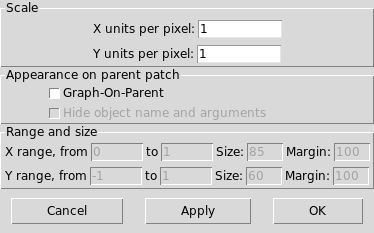
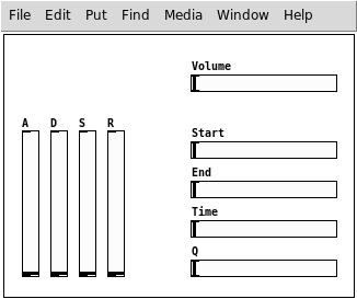
Check the Graph-On-Parent option and press OK. The rectangle that appears now in your canvas is the area that will be shown in the parent patch. For now, if you check your main patch you will see a gray rectangle. This happens because the content of the rectangle is not rendered while the subpatch is opened. After you close the subpatch window, you will see whatever was inside of that rectangle instead of just a gray color.
Open the subpatch Properties again. You need to adjust the Margin and Size values. You can think of the X and Y Margin values as the X and Y coordinates of the top-left corner of the rectangle. Set an appropriate size and then try to put all your sliders inside the rectangle, because the sliders are the only objects that the user will need to interact with. You may also want to enable the Hide object name and arguments. If you don't check this option you will see a label with the name of the object in the top-left corner of the rectangle.
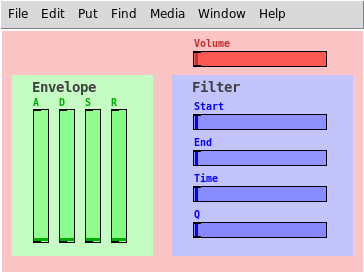
If you close the subpatch and take a look at you main patch, you will see a very simple interface with the sliders and without the ugly and confusing connections.
Canvas
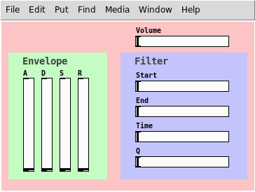
To better organize your interface you can use the Canvas object (Ctrl+Shift+C). It is possible to do a lot of stuff with this object, but we are going to use it as a simple colored rectangle with an optional label.
Open your subpatch and place a Canvas object. Now select every other object leaving the canvas out of the selection, then cut (Ctrl+X) and paste (Ctrl+V). The reason why you need to do that is because the last object to be placed always appear on top of the other objects and we want the canvas in the background. Now that it is in the background you can simply open its properties and select a color, an optional label and set its size. You can use as many of these as you want on top of each other.
Color
You probably have already noticed this, but you can change colors of some objects just like you did with the canvas. Just open the Properties of a given object and you will see which colors you can change. In this case, we will change only the color of the sliders.
Conclusion
That's it, we're done. I hope you had some fun and learned something by following this tutorial. This synthesizer is very poor if compared to any synthesizer you will find out there, but you can make something interesting and unique if you invest some time to learn and to implement your ideas.
I'll list here some ideas of projects that you can try to do by yourself to make your synthesizer more interesting.
-
Add a preset feature. Pure Data can manipulate files, meaning that you can save and load presets. You can use Pure Data's help to search for the objects that deal with files.
-
Make a better envelope for the filter. Instead of only Start and End, you can have a variation of the ADSR envelope or anything else you can imagine to make the sound more interesting.
-
Add a waveform selector, where you can select other kinds of wave instead of always using sawtooth. You can have square, sine, triangle and noise, for example. (The sine wave will not work well with the filter, because it does not contain harmonics)
-
Add an option to make the filter frequencies relative to the note played, instead of always using absolute frequencies.
-
Add a vibrato with a slider to control it. Also, optionally make it controllable by the MIDI controller.
-
Add an option to use it as a monophonic synthesizer with glide / glissando between notes.
-
Add additive synthesis capabilities by allowing more than one waveform to be used together. You can also make the second oscillator be at some interval from the first.
-
Add modulation. If you have no idea about what this is, search for Frequency Modulation and Amplitude Modulation (FM and AM).
-
Add a cool graph that shows the waveform of what you are playing in real time. You'll need to learn how to use arrays.
-
Change the MIDI channel that the synthesizer will "receive". By making this (and some other adjustments, like change the names of sends and receives to use the $0 variable) you should be able to launch various instances of the synthesizer with different sounds and play them by using different MIDI channels.
I'll not teach how to do any of these (I have done some of these, but I don't think I have the patience to even try some of the others) but if I see a lot of interest in some particular feature, I may write some kind of Appendix to this tutorial in the future.
Here's a picture of a synthesizer that I created when I was learning Pure Data. It has some of the features listed above, but not a lot of them.
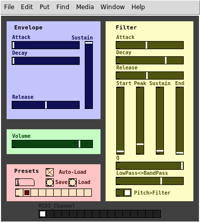
Bye!
Written by Eduardo Mezêncio